Wheel Collider
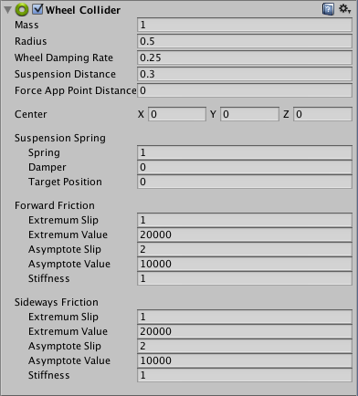
Switch to ScriptingThe Wheel Collider is a special collider for grounded vehicles. It has built-in collision detection, wheel physics, and a slip-based tire friction model. It can be used for objects other than wheels, but it is specifically designed for vehicles with wheels.

Properties
| Property: | Function: |
|---|---|
| Mass | The Mass of the wheel. |
| Radius | Radius of the wheel. |
| Wheel Damping Rate | This is a value of damping applied to a wheel. |
| Suspension Distance | Maximum extension distance of wheel suspension, measured in local space. Suspension always extends downwards through the local Y-axis. |
| Force App Point Distance | This parameter defines the point where the wheel forces will applied. This is expected to be in metres from the base of the wheel at rest position along the suspension travel direction. When forceAppPointDistance = 0 the forces will be applied at the wheel base at rest. A better vehicle would have forces applied slightly below the vehicle centre of mass. |
| Center | Center of the wheel in object local space. |
| Suspension Spring | The suspension attempts to reach a Target Position by adding spring and damping forces. |
| Spring | Spring force attempts to reach the Target Position. A larger value makes the suspension reach the Target Position faster. |
| Damper | Dampens the suspension velocity. A larger value makes the Suspension Spring move slower. |
| Target Position | The suspension’s rest distance along Suspension Distance. 1 maps to fully extended suspension, and 0 maps to fully compressed suspension. Default value is 0.5, which matches the behavior of a regular car’s suspension. |
| Forward/Sideways Friction | Properties of tire friction when the wheel is rolling forward and sideways. See the Wheel Friction Curves section below. |

Details
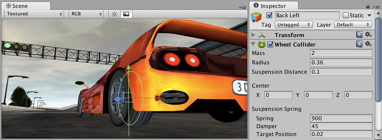
The wheel’s collision detection is performed by casting a ray from Center downwards through the local Y-axis. The wheel has a Radius and can extend downwards according to the Suspension Distance. The vehicle is controlled from scripting using different properties: motorTorque, brakeTorque and steerAngle. See the Wheel Collider scripting reference for more information.
The Wheel Collider computes friction separately from the rest of physics engine, using a slip-based friction model. This allows for more realistic behaviour but also causes Wheel Colliders to ignore standard Physic Material settings.
Wheel collider setup
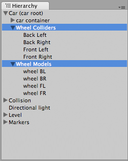
You do not turn or roll WheelCollider objects to control the car - the objects that have the WheelCollider attached should always be fixed relative to the car itself. However, you might want to turn and roll the graphical wheel representations. The best way to do this is to setup separate objects for Wheel Colliders and visible wheels:

Note that the gizmo graphic for the WheelCollider’s position is not updated in playmode:

Collision geometry
Because cars can achieve large velocities, getting race track collision geometry right is very important. Specifically, the collision mesh should not have small bumps or dents that make up the visible models (e.g. fence poles). Usually a collision mesh for the race track is made separately from the visible mesh, making the collision mesh as smooth as possible. It also should not have thin objects - if you have a thin track border, make it wider in a collision mesh (or completely remove the other side if the car can never go there).

Wheel Friction Curves
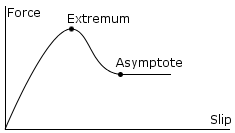
Tire friction can be described by the Wheel Friction Curve shown below. There are separate curves for the wheel’s forward (rolling) direction and sideways direction. In both directions it is first determined how much the tire is slipping (based on the speed difference between the tire’s rubber and the road). Then this slip value is used to find out tire force exerted on the contact point.
The curve takes a measure of tire slip as an input and gives a force as output. The curve is approximated by a two-piece spline. The first section goes from (0 , 0) to (ExtremumSlip , ExtremumValue), at which point the curve’s tangent is zero. The second section goes from (ExtremumSlip , ExtremumValue) to (AsymptoteSlip , AsymptoteValue), where curve’s tangent is again zero:

The property of real tires is that for low slip they can exert high forces, since the rubber compensates for the slip by stretching. Later when the slip gets really high, the forces are reduced as the tire starts to slide or spin. Thus, tire friction curves have a shape like in the image above.
| Property: | Function: |
|---|---|
| Extremum Slip/Value | Curve’s extremum point. |
| Asymptote Slip/Value | Curve’s asymptote point. |
| Stiffness | Multiplier for the Extremum Value and Asymptote Value (default is 1). Changes the stiffness of the friction. Setting this to zero will completely disable all friction from the wheel. Usually you modify stiffness at runtime to simulate various ground materials from scripting. |
Hints
- You might want to decrease physics timestep length in Time Manager to get more stable car physics, especially if it’s a racing car that can achieve high velocities.
- To keep a car from flipping over too easily you can lower its Rigidbody center of mass a bit from script, and apply “down pressure” force that depends on car velocity.